(This project is part of the Duke ECE350 class. Contributed by Chengyang Zhou and John Zehr. Supervised by Dr. John Board.)
My girlfriend and I both love driving. We go on road trips and drive just for the fun of it. Sadly, we don’t get to enjoy that fun all the time cuz we don’t have a car yet, so I decided to build this simulator. Plus, excellent driver she is she misses one key skill: parallel parking. Hopefully with this realistic driving simulator she can finally learn to parallel park (and match my unparalleled driving skills).
Overview
A realistic driving simulator should at minimum have a steering wheel, a gas and brake pedal, and a car to drive with. The user should have the ability to shift gears, at least between P-R-N-D. It is also good to have a display that shows vital info (e.g. speed, gear, direction).
Here is the project overview organized in the sensor-control-communication-actuator framework:
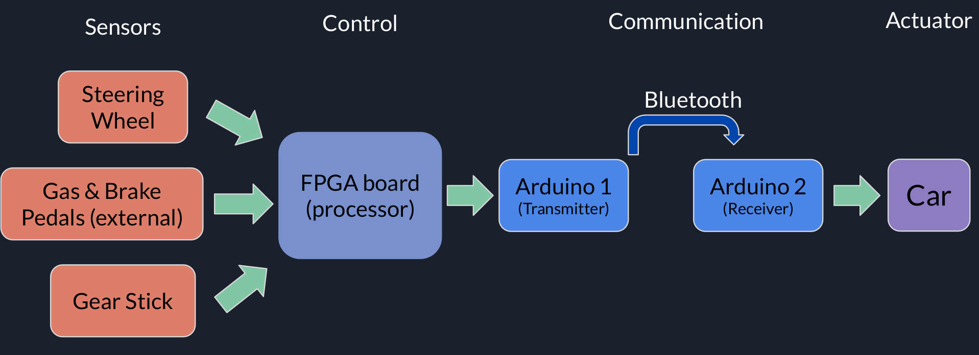
Data is extracted from the three main sensors and gets processed in the control unit. The control unit in this project is a self-made 5-stage MIPS-like processor mounted onto an FPGA board. More details about the processor will be described at the end. For now consider it to be a blackbox that processes given inputs and sends outputs to data transmission units. To ensure wireless communication we use bluetooth low-energy to transmit and receive all data in this project. These data contain commands that control a DC-motor toy car.
Components
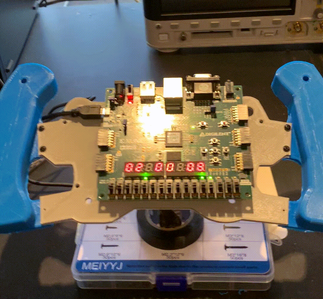
1.Nexys A7 FPGA board x1
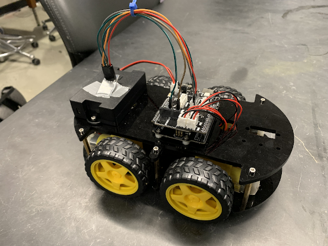
2.DC-motor car (with motor driver chip) x1
3.NRF24L01 bluetooth module x2
4.RP-S40 pressure sensors x2
5.Arduino UNO x2
Processor
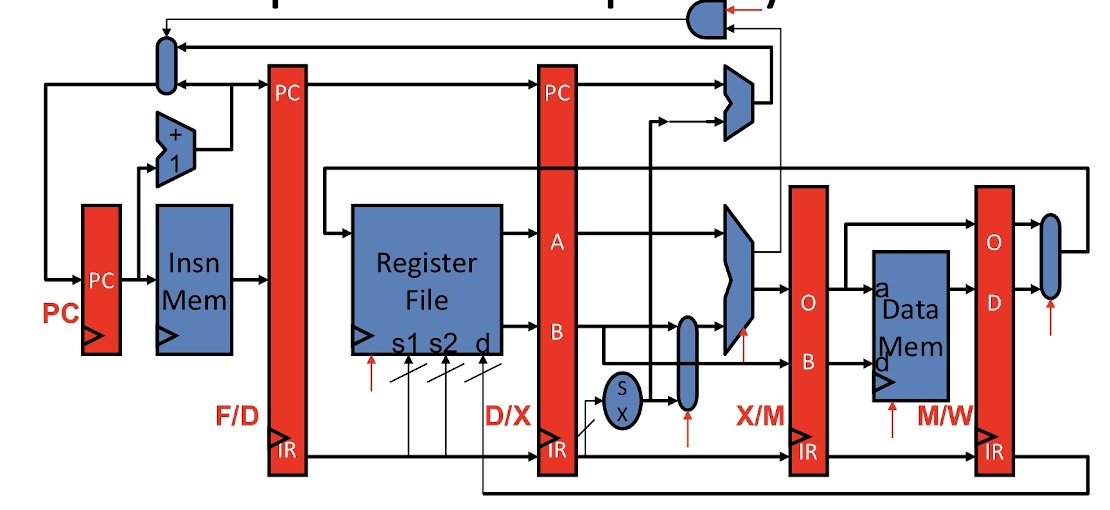
The processor we used was a 32-bit MIPS-like 5-stage processor as shown by the following diagram (taken from Duke ECE350 slides). Multiplier and divider are not shown.
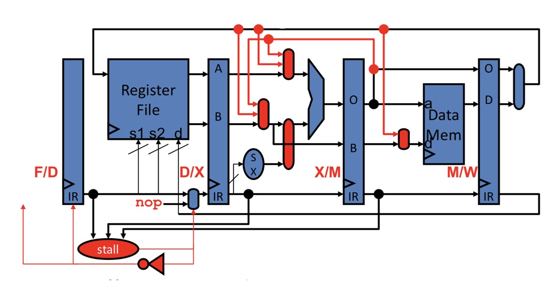
With bypass/stall logic highlighted:
Here is the ISA used:
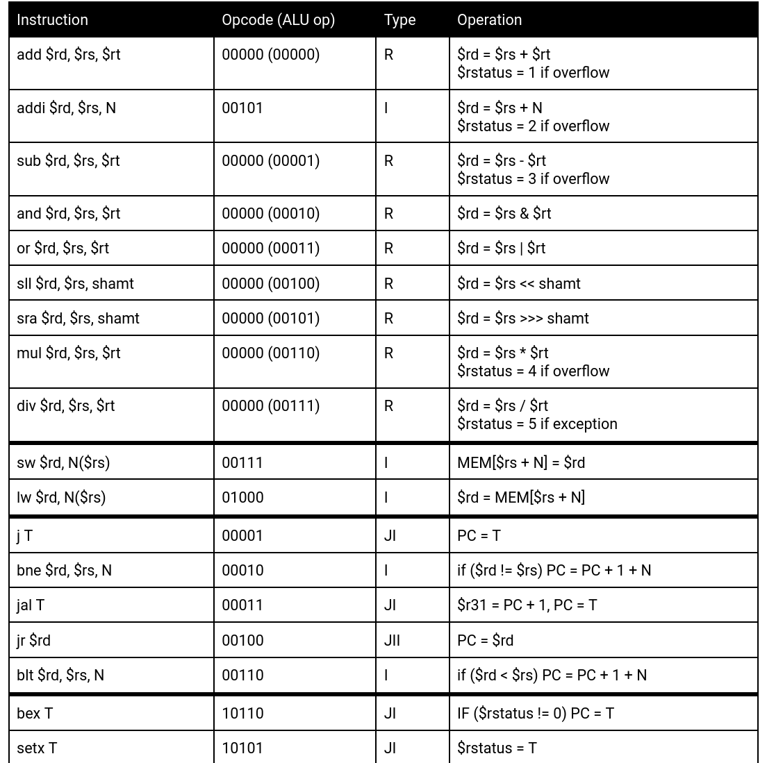
Points to note:
1.The register file contains 32 registers. $r0 is always 0, $r1 to $r30 are general purpose registers, and $r31 stores the link address of a jump-and-link instruction. In our project, we dedicated 7 individual 32-bit registers ($r23-$r29) to store raw and processed sensor data.
2.The multiplier uses modified Booth algorithm, which takes 16 cycles to complete.
3.The divider is non-restoring.
4.Memory is word-addressed.
5.Instruction and data memory are separated from each other.
6.J-type target [26:0] is extended to 32 bit using the upper bits from current programming counter value +1.
Steering Wheel
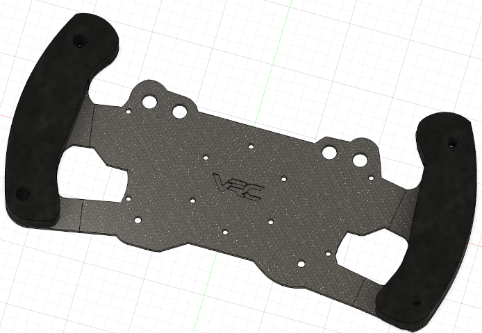
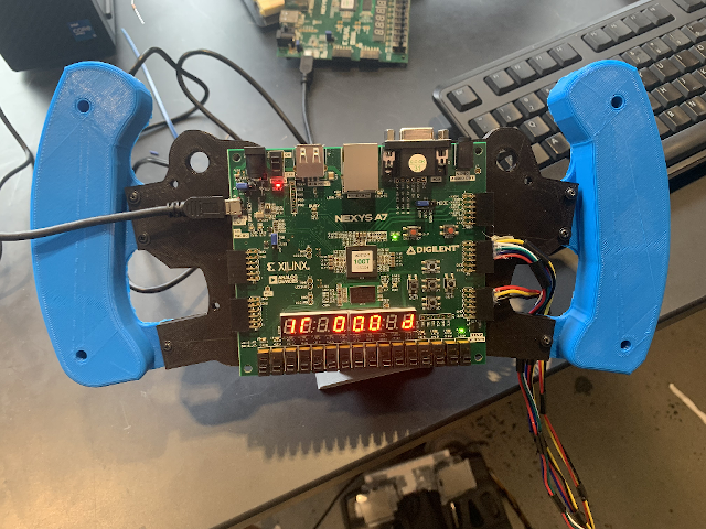
We 3D-printed a race-car steering wheel (inspired by design found online) onto which the FPGA board is installed. This steering wheel is mounted on a gimbal structure to enable rotation. The key sensor here is a 3-axis accelerometer built into the FPGA board, from which the rotation information is extracted. This information will eventually determine the steering of our car.
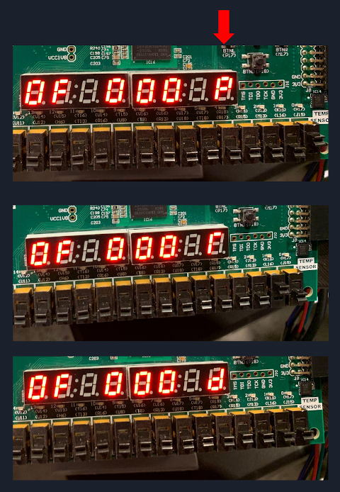
We provide three degrees of steering in each way, shown on the 7-segment display with a number and a direction. For example, 3L means sharp turn to the left and 1r means slight turn to the right. There is one additional direction 0F. which means going straight. Cars in real life seems to have a continuous range of steering angles in order to achieve fine control, which is not realistic with our accelerometer, which uses a 4-bit 2s complement number to encode the entire 180-degree spectrum.
This is our final steering wheel. “1r” here means a slight turn to the right.
Gas/Brake Pedal
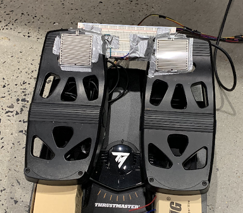
Gas and brake pedals are implemented using two pressure sensors. These sensors maps forces to a 10-bit unsigned integer which can be read using Arduino’s analogRead(). This Arduino board then feeds the number to the FPGA board for further processing.
The gas pedal readings are near-continuous to provide the realism of gradual acceleration. The brake, however, is modeled as a binary input, which means pressure over a certain threshold stops the car completely.
(For realism and aesthetic purposes, I placed them on my flight simulator rudder pedals :)
Gear Shift
Due to time constraints, we were unable to complete a mechanical gearstick for our car, so we used 2 onboard switches (the 2 rightmost switches on the Nexys A7 board) to encode P-R-D. (N is not very useful for our purpose). When the rightmost switch is on, the car is parked, as shown by the letter “P” on the 7-segment display. In this mode, no matter how hard the gas pedal is pressed, the car will remain still. When the rightmost switch is off, the 2nd rightmost switch decide whether the car is going forward or reverse, shown by “D” and “r” respectively.
Bluetooth communication
All raw inputs are processed by our 5-stage processor and then fed an Arduino, which is used as the transmitter. It sends data packets via Bluetooth Low Energy. The car then receives the data and performs corresponding actions. This toy car uses 4 independently driven DC motors controlled by a TB6612 motor driver chip. Turning is achieved using speed differences between the wheels.
Demo
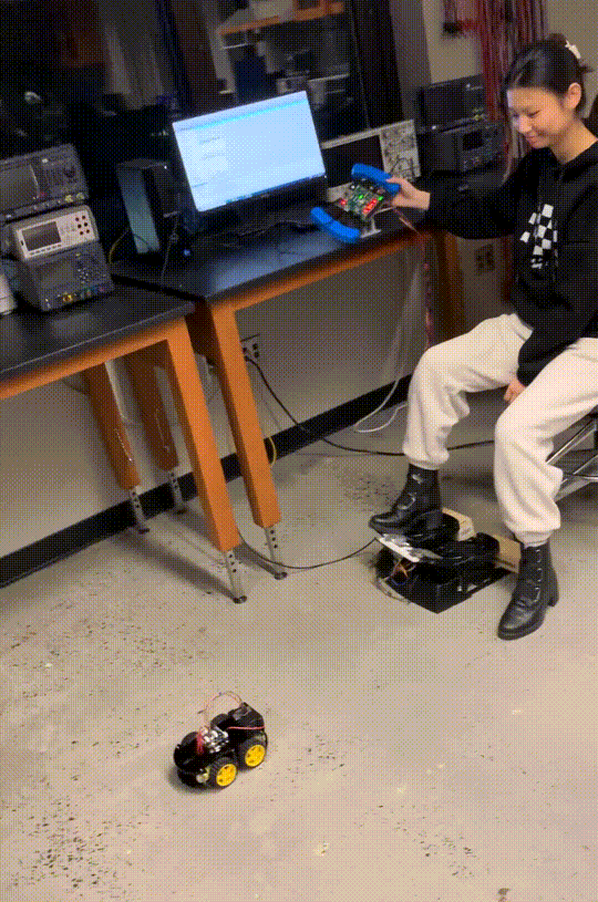
Here is our final driving simulator!
Github repo: https://github.com/zhoulele12/BIM005DriveSim